Ultra Violet Lithography Process - Mechanical
Repurposing a 4K DMD Projector for Maskless Photolithography
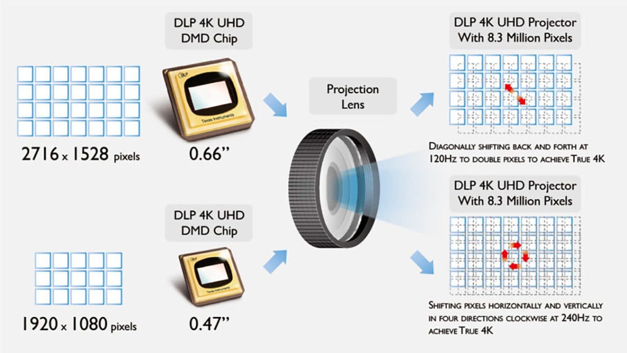
Digital micromirror devices (DMDs) have become a popular foundation for low-cost, high-resolution maskless photolithography systems. Modern 4K consumer projectors pack extremely capable DMDs, high-speed control electronics, and well-engineered thermal and mechanical structures-all at a fraction of the cost of industrial exposure tools.
This post outlines how to repurpose a deconstructed 4K DMD projector for maskless photolithography by:
- Removing the projection/magnification optics
- Bypassing the internal visible-light source
- Injecting an external 405 nm illumination path
- Preserving critical subsystems (notably the color wheel) required for correct DMD operation
System Architecture: What Matters and What Doesn't
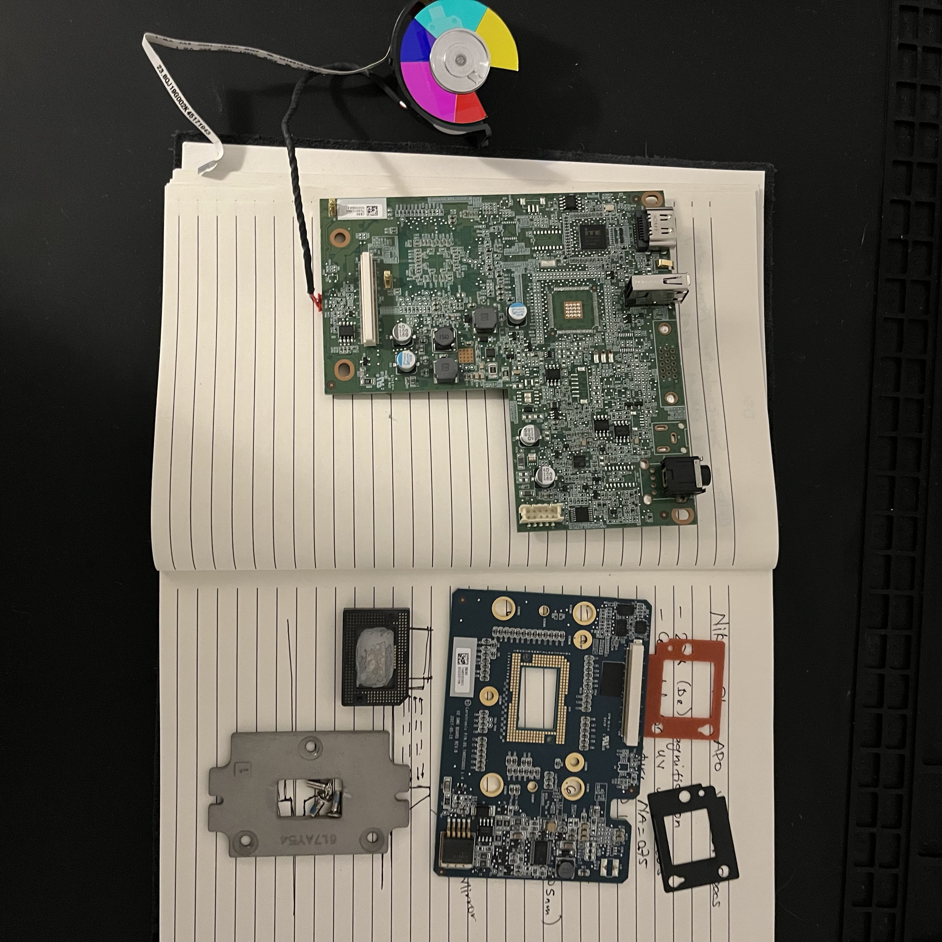
At a high level, the projector breaks down into five functional blocks:
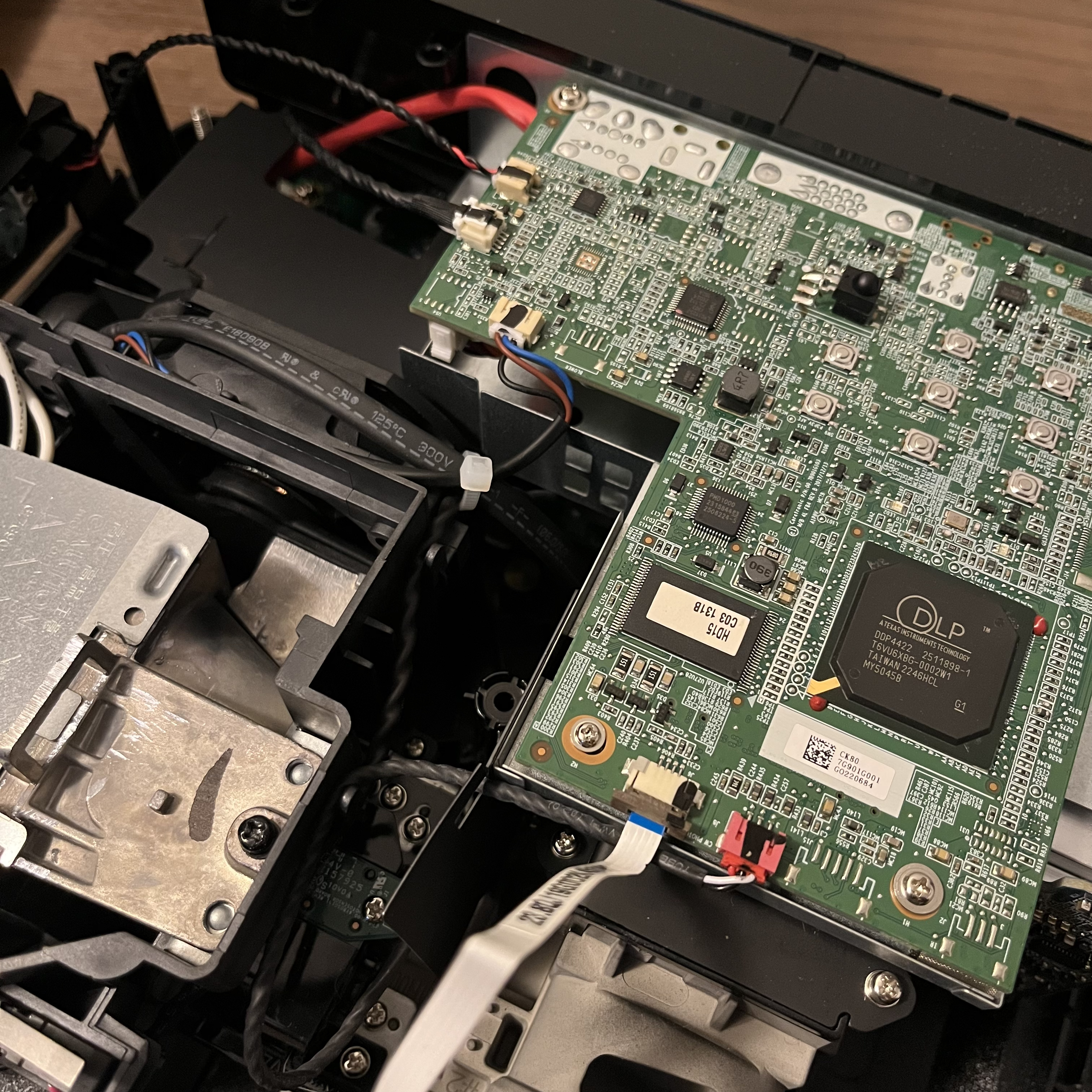
- DMD + controller PCB
- Illumination subsystem (lamp/LED + integrator optics)
- Color wheel and sensor
- Projection lens assembly (magnification optics)
- Power, thermal, and mechanical infrastructure
For maskless lithography, only (1), (3), and parts of (5) are truly essential.
Step 1: Removing the Projection Optics (Magnification Path)
Consumer projectors are designed to throw a magnified image several meters onto a screen. For lithography, this is undesirable-you want either:
- 1:1 imaging onto a substrate, or
- A custom demagnification ratio using precision UV optics
What to Remove
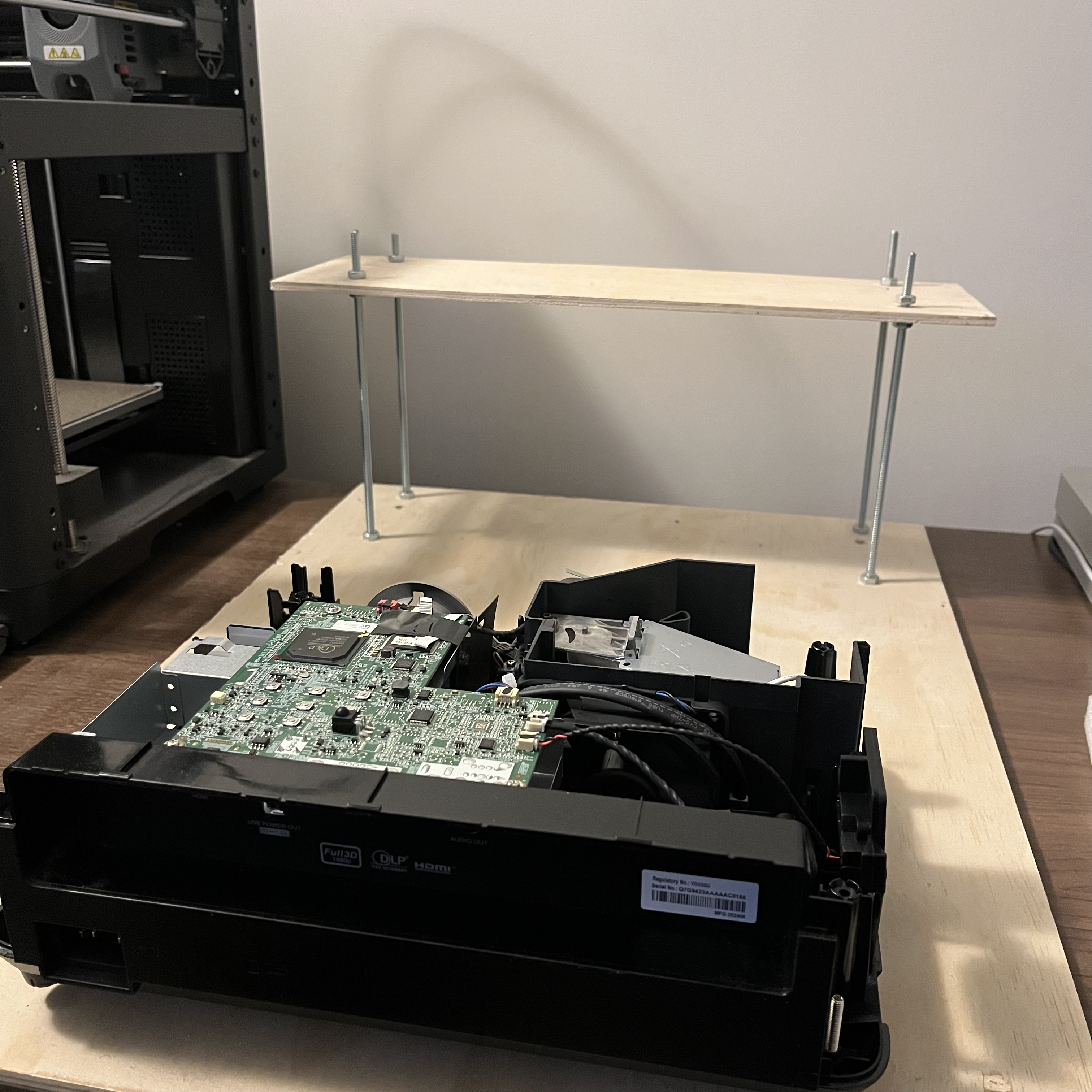
From the teardown images:
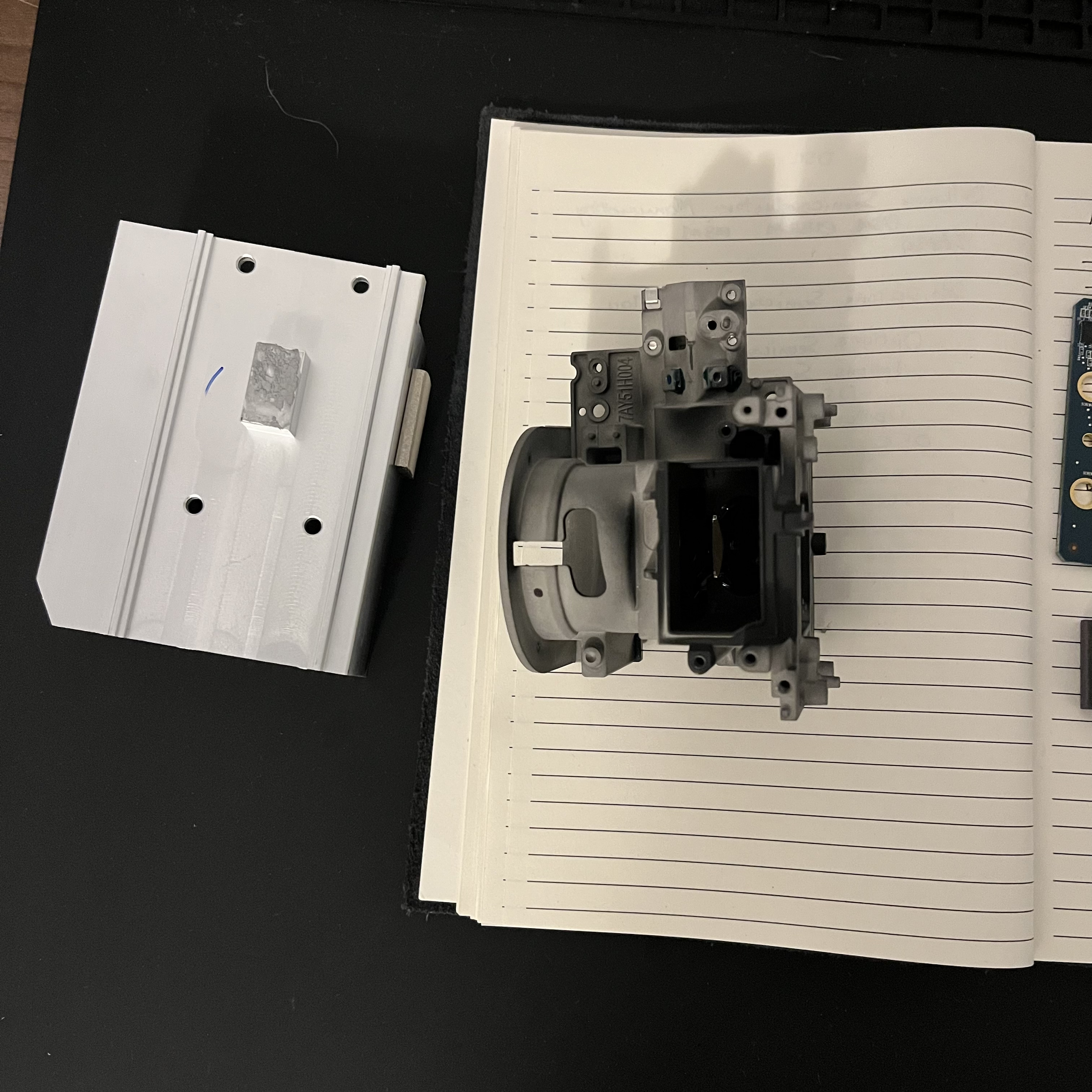
- The entire projection lens barrel can be removed.
- Any autofocus motors or zoom assemblies are no longer needed.
- The metal lens cage and its mounting brackets can be discarded.
What to Keep
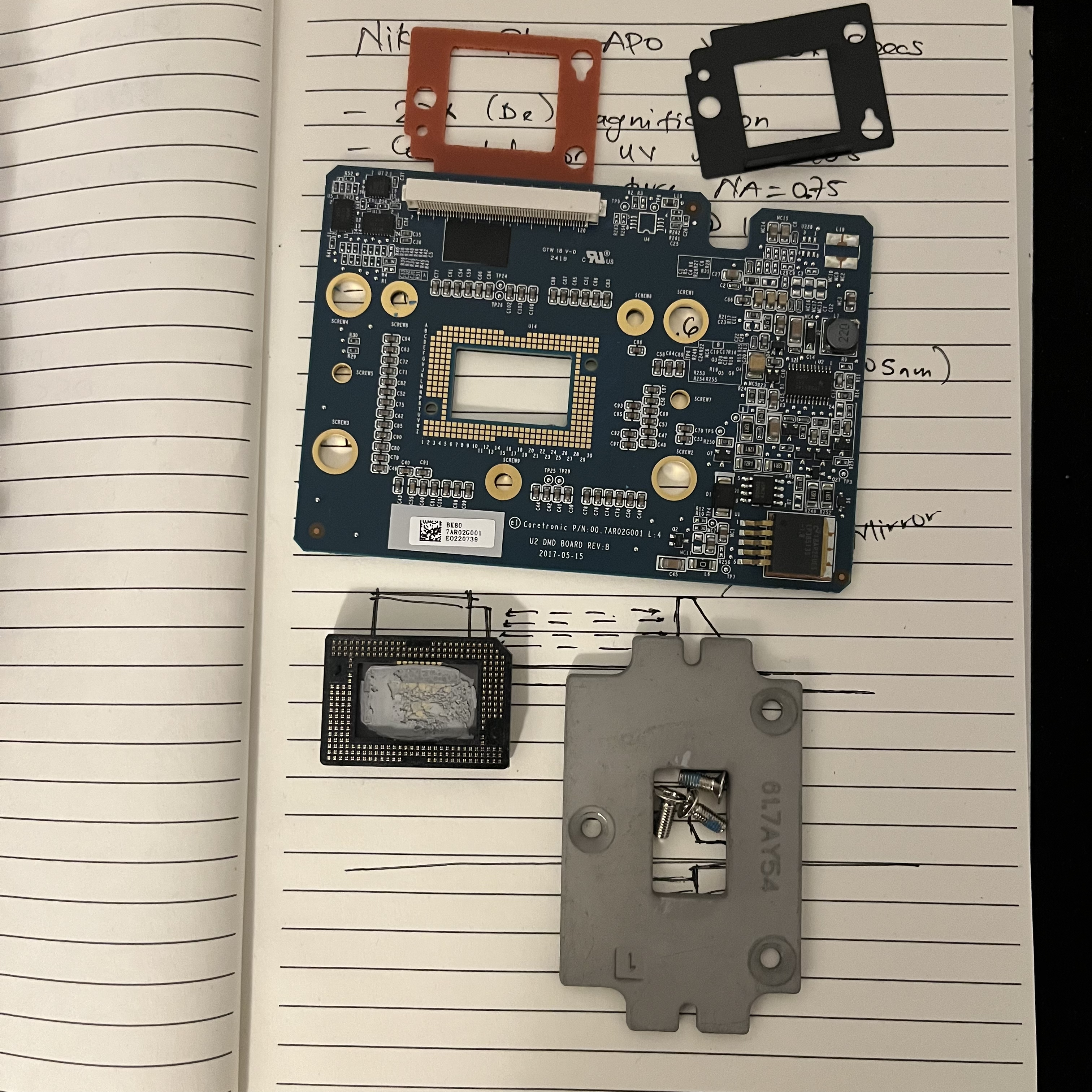
- The DMD itself, mounted on its heatsink and carrier.
- The final fold mirrors or prisms immediately adjacent to the DMD if they are part of the DMD mounting geometry (some designs integrate them mechanically).
After removal, the DMD face should be optically accessible, ideally normal to your intended exposure plane.
Do not disturb the DMD mounting pressure or heatsink preload. Even slight mechanical stress can cause mirror tilt errors or thermal failure.
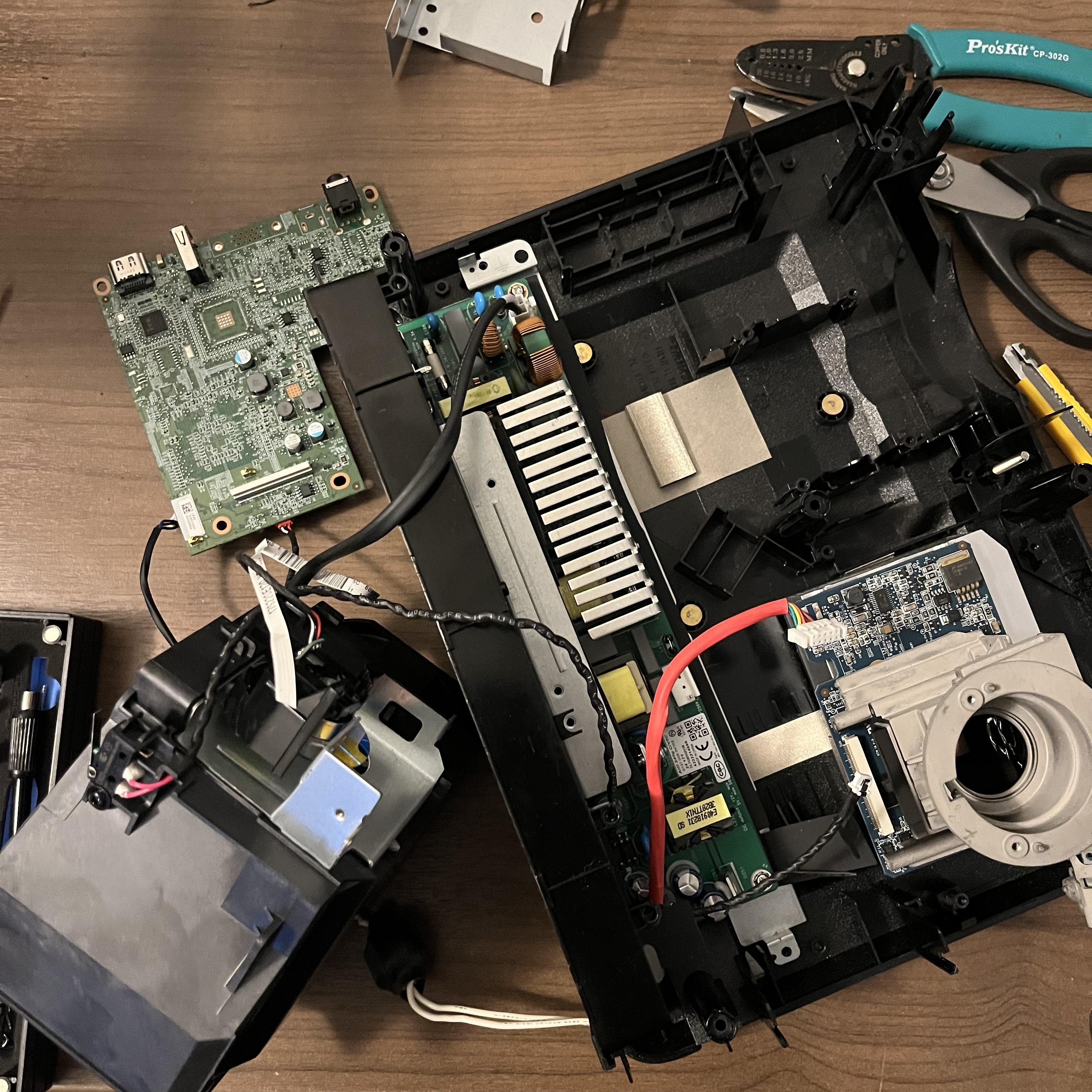
Step 2: Removing the Internal Light Source
The internal lamp or LED assembly is optimized for broadband visible light and typically includes:
- A high-power lamp or RGB LED module
- Reflectors and condenser lenses
- Light tunnel / integrator rod
For UV lithography at 405 nm, this entire subsystem becomes a liability.
Safe Removal
- Disconnect the lamp/LED power lines at the PSU.
- Remove the lamp housing and associated reflectors.
- Retain the light tunnel / integrator rod if it is transmissive at 405 nm (many glass tunnels are acceptable at near-UV).
If the integrator is absorptive or glued with UV-opaque epoxy, replace it with:
- A fused-silica rod
- Or a homogenized free-space illumination setup
Step 3: Injecting an External 405 nm Light Source
Your external UV source (laser diode or high-power LED) must illuminate the DMD at the correct angle and numerical aperture.
Key Optical Constraints
- DMDs are designed for off-axis illumination (typically 20–24°).
- The micromirrors have ON and OFF tilt states-illumination angle determines contrast.
- Overfilling the DMD aperture reduces contrast and increases stray exposure.
Recommended Setup
- Collimated 405 nm source
- Beam expander → integrator → condenser optics
- Adjustable kinematic mount to fine-tune angle and focus
The goal is uniform irradiance across the DMD active area with minimal angular spread.
Step 4: Why the Color Wheel Must Stay
This is the most commonly misunderstood part of projector repurposing.
Even though you are using monochromatic 405 nm light, the color wheel is not optional in most consumer projectors.
Why It Exists (Beyond Color)
- The projector firmware expects color-wheel index timing.
- DMD bitplanes are synchronized to color segments.
- Removing the wheel often causes:
- No image output
- Reduced duty cycle
- Fault or shutdown states
Best Practice Options
Option A: Keep the Wheel Spinning
- Leave the wheel mechanically intact.
- Let it free-run as designed.
- Ignore color filtering-your 405 nm source dominates anyway.
Option B: Replace with a Dummy Wheel
- Fabricate a clear disk with timing marks.
- Maintain the same rotational inertia and sensor triggering.
Option C: Firmware Hacking (Advanced)
- Reverse-engineer wheel timing signals.
- Emulate them electronically.
- Risky, time-consuming, but removes mechanical noise.
For most lithography setups, Option A is the fastest path to success.
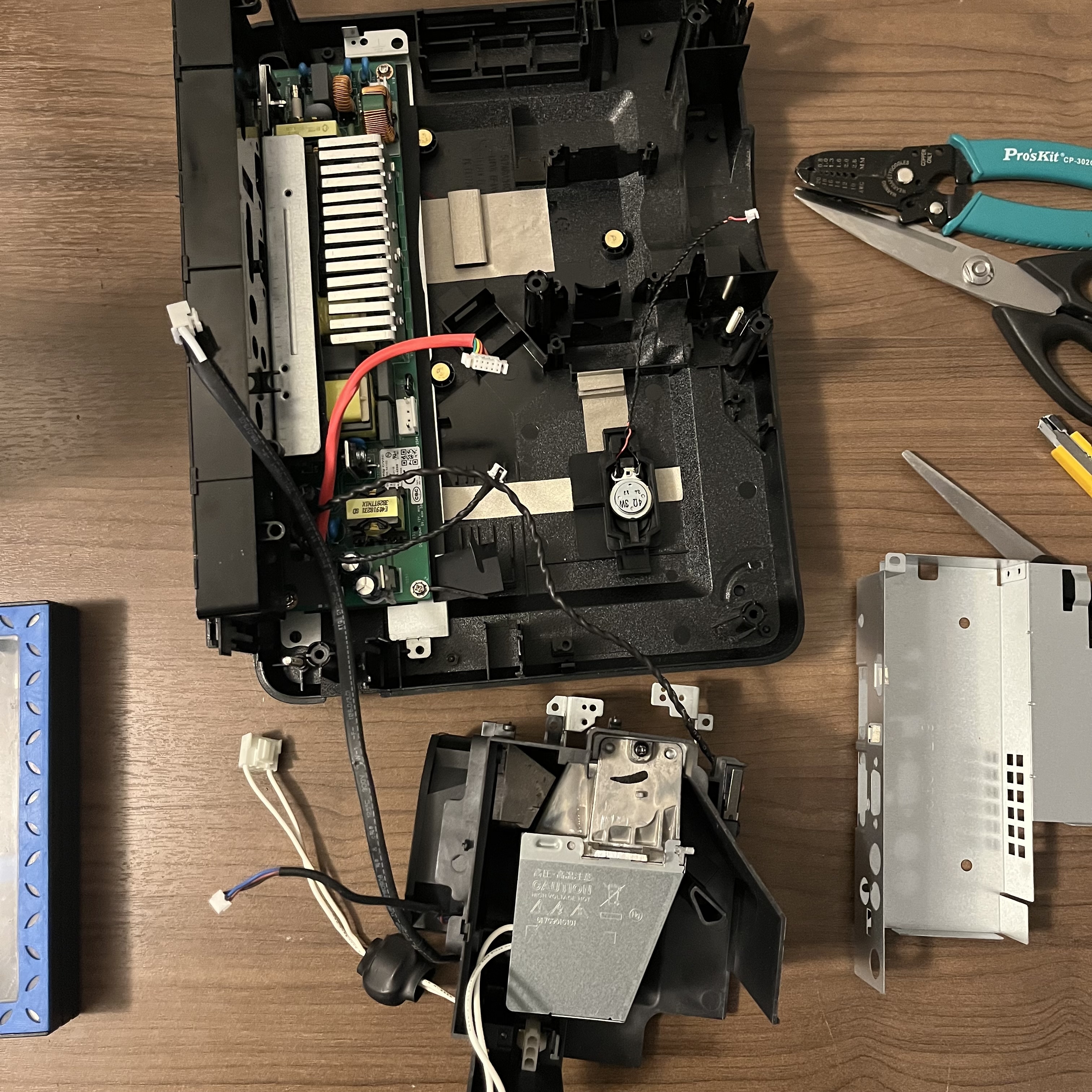
Step 5: Thermal and Electrical Considerations
Even without the lamp, the DMD dissipates significant heat.
Thermal
- Retain the original heatsink and fan.
- Maintain airflow paths shown in the chassis.
- Monitor DMD case temperature-UV operation often increases absorption.
Electrical
- The projector PSU is still useful:
- DMD core voltages
- Controller logic
- Color wheel motor drive
- Unused lamp rails can be left disconnected or lightly loaded if the PSU expects feedback.
Step 6: Image Pipeline and Lithography Control
With the optics modified, the projector still thinks it's displaying video.
Practical Control Strategy
- Drive the projector via HDMI or eDP.
- Use grayscale bitplanes to control exposure dose.
- Disable all image processing:
- Keystone
- Dynamic contrast
- Motion smoothing
For best results:
- Output native 4K resolution
- Use 1-bit or low-bit grayscale masks
- Synchronize exposure time with frame timing
Final Thoughts
Consumer 4K DMD projectors are remarkably close to being lithography tools out of the box. The key is knowing what not to remove.
Remove:
- Projection optics
- Internal light source
Keep:
- DMD + controller
- Color wheel + sensor
- Thermal infrastructure
With careful optical injection and respect for the projector's timing assumptions, you end up with a compact, high-resolution, maskless photolithography engine capable of micron-scale features-without touching a cleanroom mask.