Technical Documentation
This MCU is responsible for polling IMU sensors at a high-rate, listening for incoming radio commands and actively stabilizing the aircraft about a desired setpoint.
The Flight Control Computer (FCC) is based on the RP2040 microcontroller clocked @ 133MHz this is fast enough to run the external PID control loop as well handle all the calculations needed for reliable attitude estimation.
PCB View
Interactive BOM
info
An interactive BOM to aid in assembly can be found here
Hardware Design
The Flight Control System consists of:
note
The datasheets for all the components used can be found here
Power
The RP2040 chip requires two different voltage supplies 3.3V (for I/O's) and 1.1V (for the chips digital core). The main power source for this embedded system is a 3-6S LiPo Battery. Both MCU's are powered via a single 5V USB connection despite needing seperate USB connectors to program, this done to aid debugging.
Requirements
- Step-down LiPo 11.2-26V DC Input to 5V for actuators
- Supply both MCU's with 3.3V from either USB_VBUS or VCC.
Battery & 5V Power Supply
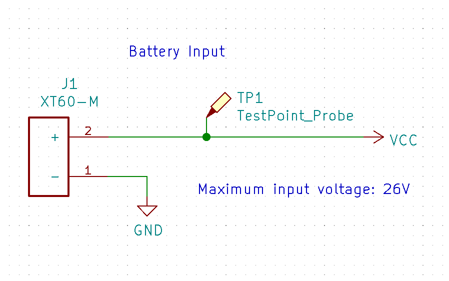
To step down 11.2V from the LiPo Battery to 5V a DC/DC Buck Regulator rated to a max. of 28V is needed.
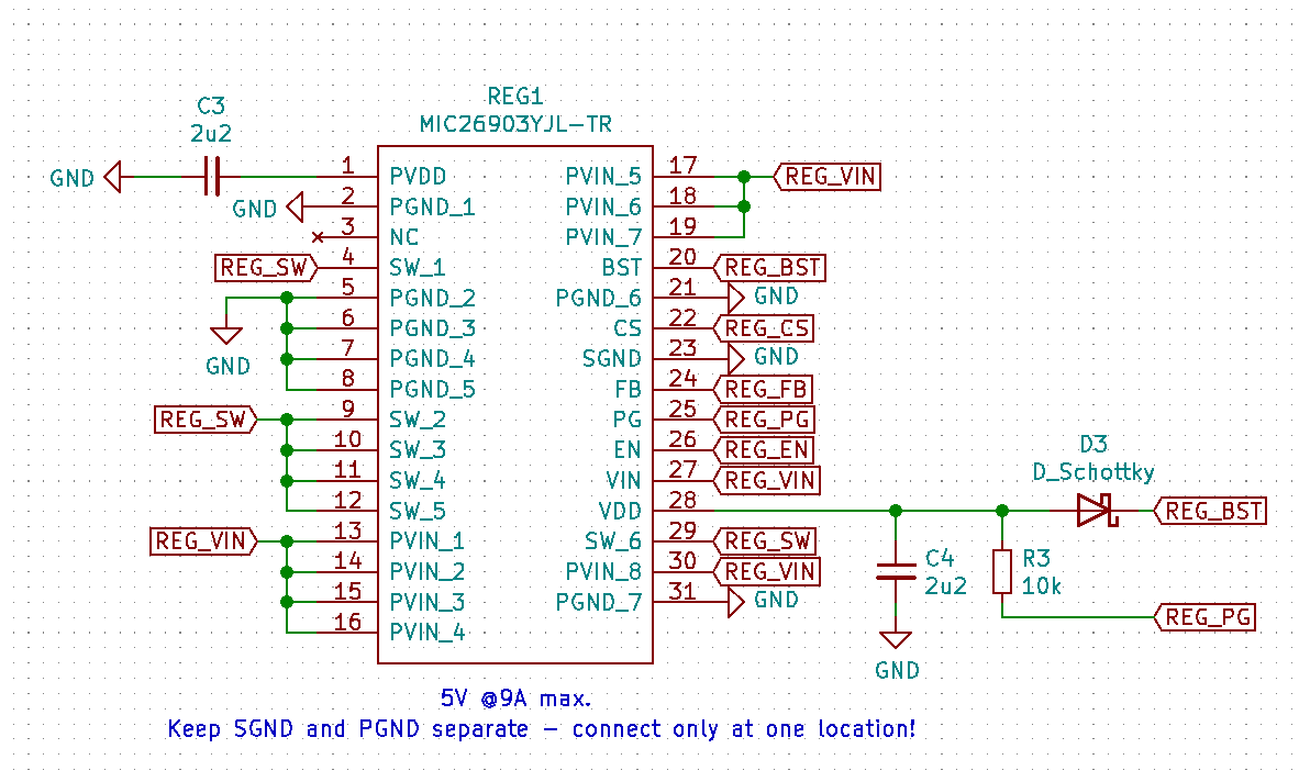
The Micrel MIC26903 is used to supply 5V @ 8A to all the actuators and 3.3V regulators.
 |
|---|
| Figure 1: Battery |
 |
|---|
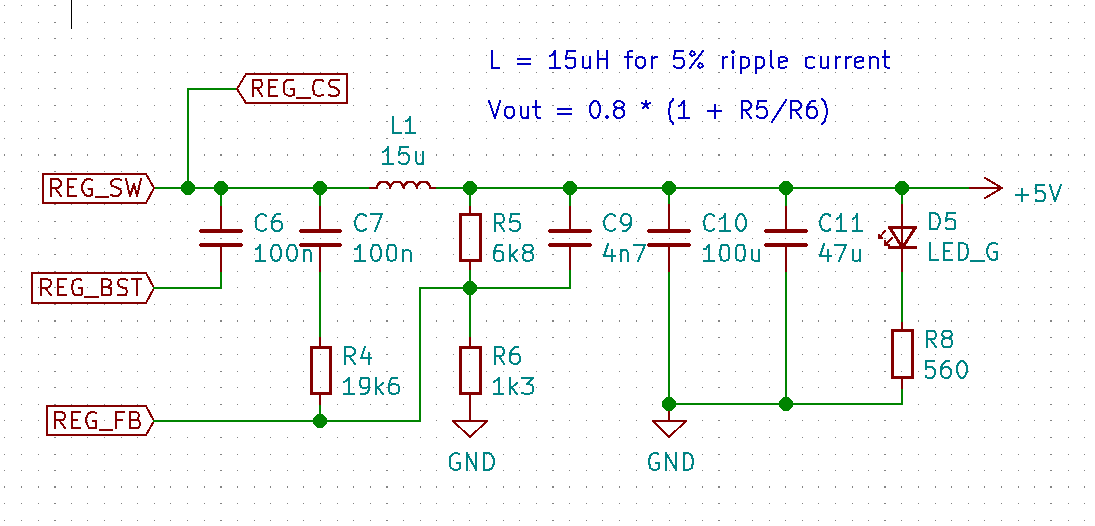
| Figure 2: Buck Regulator input filtering |
 |
|---|
| Figure 3: Buck Regulator |
 |
|---|
| Figure 4: Buck Regulator output filtering |
3.3V Power
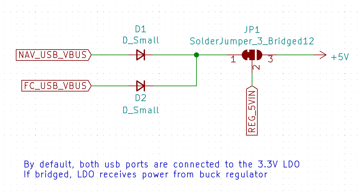
Both USB ports are connected to a LDO providing 3.3V @2A to both MCU's and their peripherals.
 |
|---|
| Figure 5: Solder-jumper for LiPo 5V input |
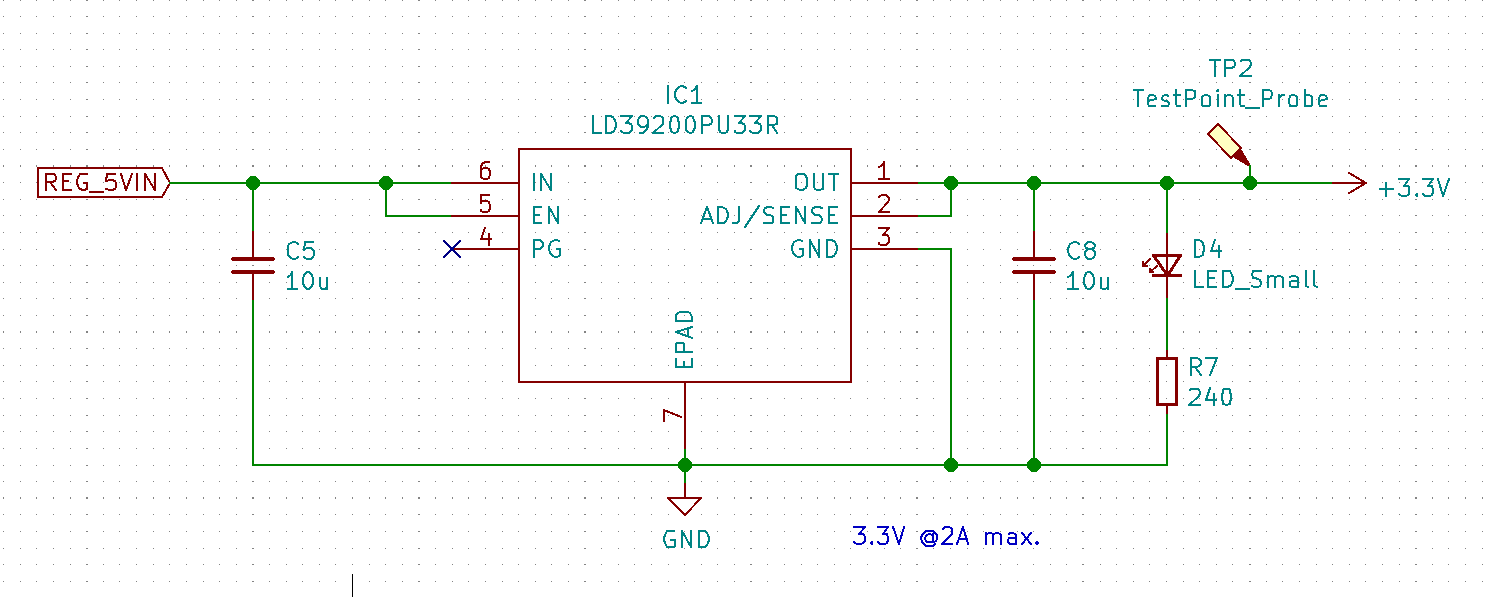 |
|---|
| Figure 6: 3.3V Low Dropout Voltage Regulator (LDO) |
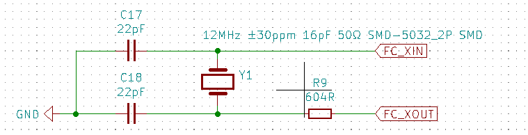
Crystal Oscillator
Load capacitance calculation
Where is the stray capacitance in the oscillator circuit, and can be estimated to 5pF.
The external resistor value can than be calculated by the following formula:
 |
|---|
| Figure 7: 12MHz 16pF Crystal Oscillator |
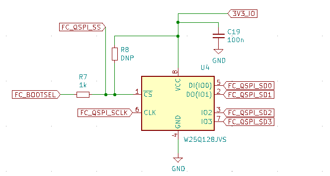
Flash Storage
In order to be able to store program code which RP2040 can boot and run from, we need to use a flash memory, specifically, a quad SPI flash memory. The device chosen here is an W25Q128JVS device, which is a 128Mbit chip (16Mbyte). This is the largest memory size that RP2040 can support.
 |
|---|
| Figure 8: W25Q128JVS 128Mbit flash (16Mbyte) |
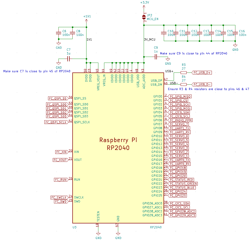
MCU
RP2040 is a 56 pin, 7x7mm QFN (Quad Flat No-leads) package with a small pitch (0.4mm pin-to-pin spacing).
 |
|---|
| Figure 9: RP2040 |
Sensors
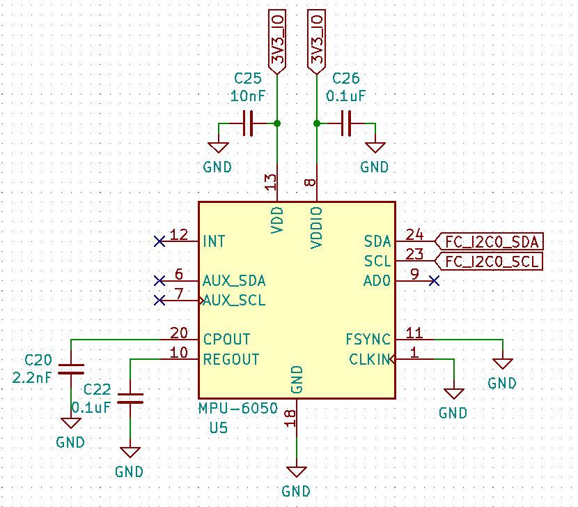
Invensense MPU6050 is the accelerometer/gyroscope sensor.
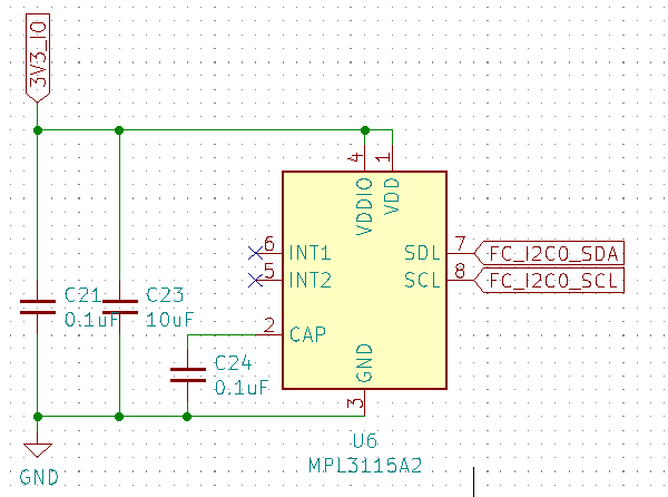
NXP MPL3115A2 is the barometric pressure sensor chosen to estimate altitude.
 |
|---|
| Figure 10: Invensense MPU6050 |
 |
|---|
| Figure 11: NXP MPL3115A2 |
Radio
The Flysky FS-iA10B receiver is used to receive RC control input signals via PPM.
Get the Flysky FS-iA10B here
// PPM Timing constants
uint32_t ppm_delta = 0;
uint32_t ppm_prev = 0;
uint32_t MIN_PPM_DELAY_BETWEEN_PACKETS = 5000; //usec
uint32_t MAX_PPM_DELAY_BETWEEN_CHANNELS = 500; //usec
int PPM_CHANNEL_INDEX = 0;
int prev_idx;
bool PPM_START = false;
// 8 Channels for FS-iA10B PPM-Output Setting. check 'config.h'
uint32_t PPM_PACKET[NUM_PPM_CHANNELS] = {};

void ppm_callback(uint gpio, uint32_t events){

    ppm_delta = time_us_32() - ppm_prev;
    ppm_prev = time_us_32();
    // Decode PPM Signal
    if (ppm_delta > MIN_PPM_DELAY_BETWEEN_PACKETS){
        PPM_START = true;
    }
    else if (ppm_delta < MAX_PPM_DELAY_BETWEEN_CHANNELS){
        if (PPM_START){
            PPM_CHANNEL_INDEX = 0;
            PPM_START = false;
        }
        else{
            //sanity check
            if (ppm_delta){
                PPM_CHANNEL_INDEX++;
                if (PPM_CHANNEL_INDEX > NUM_PPM_CHANNELS - 1){
                    PPM_CHANNEL_INDEX = 0; // Reset index to zero
                }
            }
        }
    }
    else{
        PPM_PACKET[PPM_CHANNEL_INDEX] = ppm_delta;
    }
}

void init_radio(){
    gpio_set_irq_enabled_with_callback(PPM_PIN, GPIO_IRQ_EDGE_RISE | GPIO_IRQ_EDGE_FALL, true, &ppm_callback);
}
 |
|---|
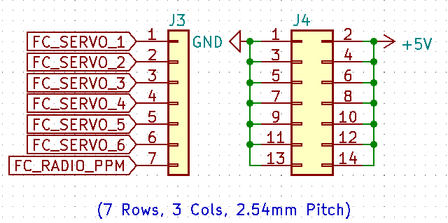
| Figure 12: Connectors |
Before First Boot
After assembling all the components.
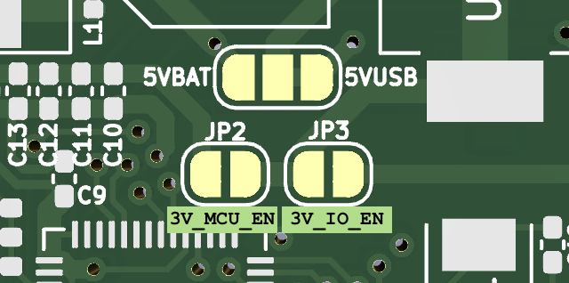
Solder jumper JP2 & JP3 only after ensuring 3.3V is the nominal voltage.
This supplies power to the MCU and peripheral components (eg. Sensors and Flash)
 |
|---|
| Figure 13: Bridge 3V_MCU_EN & 3V_IO_EN pads |
After soldering JP2 & JP3, it is safe to power the board and begin flashing firmware.
Below is a brief video showing the FC booting and completing it's LED boot sequence.
Resources
All Design files and resources can be found here